

RMCS-1101 is upgraded to a 80V 7Amp drive compatible with M880, M860 stepper drives.
RMCS-1101 is Rhino Motion Controls high power micro-stepping drive for 1.8deg Bipolar Stepper Motors. It is designed for smooth and quiet operation without compromising on torque and control at higher speeds. It has short-circuit protection for the motor outputs, over-voltage and under-voltage protection and will survive accidental motor disconnects while powered-up.
The RMCS-1101 achieves micro-stepping using a synchronous PWM output drive and high precision current feedback and this is absolutely silent when the motor is stopped or turning slowly. It virtually eliminates stopped-motor heating regardless of power supply voltage.
The RMCS-1101’s closed-loop control gains are calibrated on start-up based on motor characteristics and also adjusted dynamically while the motor is in motion. This control algorithm makes it capable of achieving better torque at higher speeds in comparison to comparable drives in its range.
The PULSE/STEP, DIRECTION inputs are optically isolated. Both inputs work with 2.5V, 3.3V or 5V logic drive signals. The input drive current is 5mA at 2.5V so almost all logic family (74LS, 74HC, etc.) can be used to drive these inputs. Each input provides individual anode and cathode connections to the opto-isolator allowing for multiple input drive interfaces.
Micro-Stepping Drive Features
- Smooth and quiet operation at all speeds and extremely low motor heating
- Industrial grade performance for 2-Phase Bipolar, 4-Phase and Uni-polar Stepper Motors
- Input supply voltage from 18VDc to 80VDC
- Selectable peak coil current from 1A to 7A
- Inaudible 200kHz current chopping frequency
- Selectable half-current during motor standstill to further reduce motor heating
- Selectable micro-steps up to 20000 steps per rotation for a 1.8deg stepper motor
- Higher motor torque and higher speeds achievable due to advanced loop control algorithm
- 2.5V, 3.3V and 5V compatible PULSE and DIRECTION inputs with 2-wire opto-isolated interface
- Short-circuit protection for the motor outputs, over-voltage and under-voltage protection
- LED indication for power and error states
Power and Motor Terminal Assignments
| Terminal No. | Terminal Name | Description | |||
| Terminal 1 | B- | Motor Coil Phase B- | |||
| Terminal 2 | B+ | Motor Coil Phase B+ | |||
| Terminal 3 | A- | Motor Coil Phase A- | |||
| Terminal 4 | A+ | Motor Coil Phase A+ | |||
| Terminal 5 | +V | Power +Ve (18VDC to 80VDC Max wrt. GND) | |||
| Terminal 6 | GND | Power Ground or Power –Ve | |||
Pulse and Direction Input Assignments
| Terminal No. | Terminal Name | Description | |||
| Terminal 1 | ENA- | Enable (Motor Free) -Ve optically isolated input | |||
| Terminal 2 | ENA+ | Enable (Motor Free) +Ve optically isolated input | |||
| Terminal 3 | DIR- | Direction -Ve optically isolated input | |||
| Terminal 4 | DIR+ | Direction +Ve optically isolated input | |||
| Terminal 5 | PUL- | Pulse -Ve optically isolated input | |||
| Terminal 6 | PUL+ | Pulse +Ve optically isolated input | |||
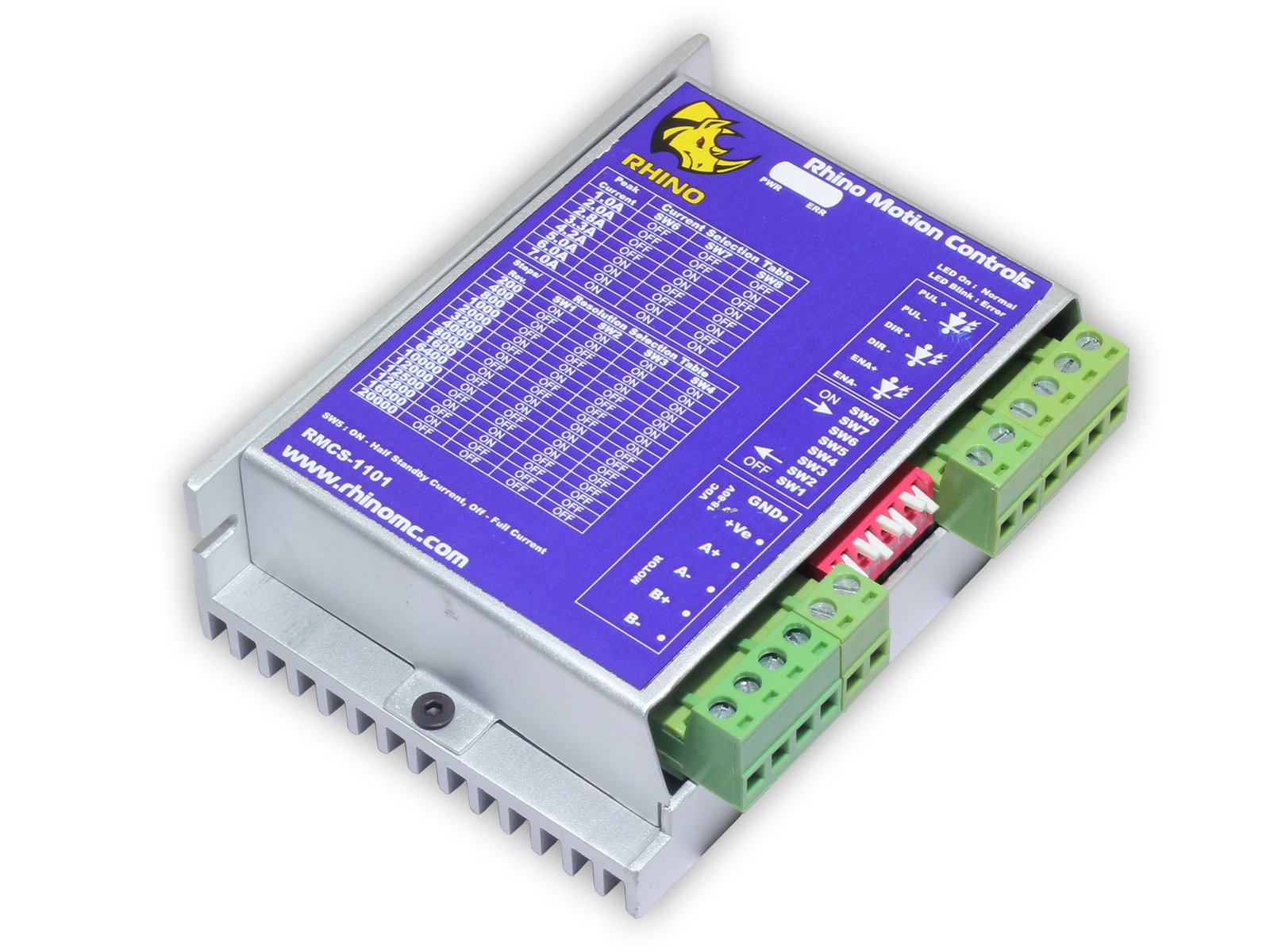
Switch Selection Table for Motor Coil Current Setting
| Peak Current | SW6 | SW7 | SW8 |
| 1.00A | OFF | OFF | OFF |
| 2.00A | OFF | OFF | ON |
| 2.80A | OFF | ON | OFF |
| 3.30A | OFF | ON | ON |
| 4.20A | ON | OFF | OFF |
| 5.00A | ON | OFF | ON |
| 6.00A | ON | ON | OFF |
| 7.00A | ON | ON | ON |
Switch Selection Table for Step Resolution Setting
| Steps/Rev | SW1 | SW2 | SW3 | SW4 |
| 200 | ON | ON | ON | ON |
| 400 | OFF | ON | ON | ON |
| 800 | ON | OFF | ON | ON |
| 1000 | OFF | OFF | ON | ON |
| 2000 | ON | ON | OFF | ON |
| 3200 | OFF | ON | OFF | ON |
| 4000 | ON | OFF | OFF | ON |
| 8000 | OFF | OFF | OFF | ON |
| 1600 | ON | ON | ON | OFF |
| 6400 | OFF | ON | ON | OFF |
| 10000 | ON | OFF | ON | OFF |
| 12000 | OFF | OFF | ON | OFF |
| 12500 | ON | ON | OFF | OFF |
| 12800 | OFF | ON | OFF | OFF |
| 16000 | ON | OFF | OFF | OFF |
| 20000 | OFF | OFF | OFF | OFF |
Switch in downward positions is ON
SW5 ON – Half-Current during Stand-still
SW5 OFF – Full-Current during Stand-still